|
This article describes Avastar Mesh related User Interface in more detail. Please note that we mostly describe what Avastar adds(!) to Blender. This document is intended as a reference guide and not as a user manual for howto work with the tools. |
Avastar Meshes |
|
|
The Avastar character serves 3 purposes:
To support the above usage scenarios, we have fully recreated the Avatar from OpenSim and similar online worlds in Blender. Here is a summary: An Avastar model is always made out of 8 separate parts.
Each Mesh part contains
Note: Material support is still a work in progress. Currently not all Avastar meshes are automatically associated to materials. |
|


Add a new Avastar Character
add -> Avastar
This will create a new female Avastar character. After a short time (typically 2-4 secs) a new Avastar character is created in the 3D View and at the current 3D cursor location .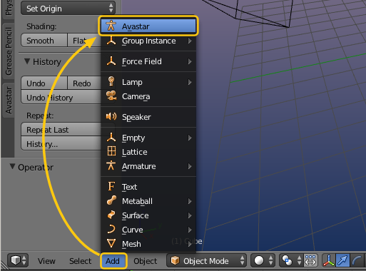

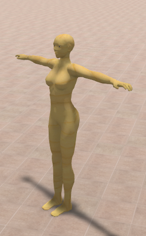
Avastar’s default Shape is compatible with SL’s default Shape.
Important: The Avastar figure is an exact representation of the SL Avatar, based on the SL Avatar definition from Linden Labs and so it is fully compatible with the character from Second Life and all similar online worlds like OpenSim for example.
We do not use any of the Ruth shapes, because there is no clear definition what Ruth is. While there is an official definition of the default shape. In SL you create the default shape from your Inventory:
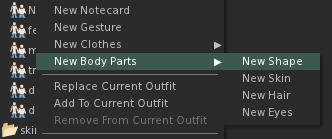
The SL default Shape (Create new Shape).
W<strong>hat you should know</strong>
- New Avastar characters can only be created when you are in Object Mode!
- A new character will be placed at the current 3D Cursor location.
- You can hide (‘h’) or remove (‘x’) not needed parts (like the skirt or the hair for example) without breaking the tools.
- You can create as many characters as you like and thus you can create multi-character animations. Multi-character animations will be explained in the reference guide.
-
The character that you know from avatar.blend or from the workbench (sometimes also named “ruth”) looks different from the default Avastar character. this is not a mistake. Further explanations can be found in the Avastar vs. Workbench Skeleton article.
Add a new Avastar Character
add -> Avastar -> With Triangles
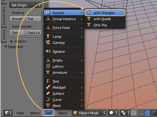
Note: The option “with Quads” is only available when you have Sparkles-pro
This will create a new female Avastar character. After a short time (typically 2-4 secs) a new Avastar character is created in the 3D View and at the current 3D cursor location .
Avastar’s default Shape is compatible with SL’s default Shape.
Important: The Avastar figure is an exact representation of the SL Avatar, based on the SL Avatar definition from Linden Labs and so it is fully compatible with the character from Second Life and all similar online worlds like OpenSim for example.
We do not use any of the Ruth shapes, because there is no clear definition what Ruth is. While there is an official definition of the default shape. In SL you create the default shape from your Inventory:
The SL default Shape (Create new Shape).
W<strong>hat you should know</strong>
- New Avastar characters can only be created when you are in Object Mode!
- A new character will be placed at the current 3D Cursor location.
- You can hide (‘h’) or remove (‘x’) not needed parts of the Avatar meshes (like the skirt or the hair for example) without breaking the tools.
- You can create as many characters as you like and thus you can create multi-character animations.
-
The character that you know from avatar.blend or from the workbench (sometimes also named “ruth”) looks different from the default Avastar character. this is not a mistake. Further explanations can be found in the Avastar vs. Workbench Skeleton article.
Custom Meshes |
|
| Although Avastar has been designed as Animation tool, we wanted to provide a reasonable tool kit for also supporting creators of rigged Custom Attachments and even entire Custom characters. But we also have started to add some support for transporting static and rigged Meshes from Blender to OpenSim or any compatible online world. | You find the main mesh support functions in the Tool shelf of the 3D View. The displayed function depend on whether you have just selected an arbitrary mesh alone (in obect mode) or together with an Avastar rig. This will be documented in more detail in the remainder of this text. |
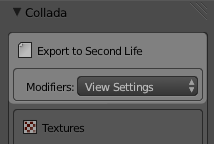
Export your Character as Collada
Hint: You usually can keep the default settings and just click on the “Collada(Avastar)(.dae)” button. A File Selector will pop up. Here you can navigate to your export directory and then export your file as a Collada file (using the file extension “.dae”)
Modifiers
By default Avastar applies all mesh changing Modifiers except the Armature Modifiers to the exported meshes. However, some modifiers have 2 sets of options, one option set is for rendering, the other option set is for the Viewport. We provide 3 options here:
- Apply according to the View Settings (the 3D Preview settings)
- Apply according to the Render Settings (the settings for Blender’s own Renderer)
- Don’t apply modifiers and only export the base mesh
The View settings will be applied by default. These settings are very closely related to the Blender Render System. In most cases you can actually just use the defaults. We will get back to this when we talk about how to use (or not use) Modifiers.
We will get to armature Modifiers in the “Create an Attachment” tutorial.
Hint: You want to display the modifier in edit mode and adjust edit cage to modifier result
Textures export (advanced)
Note: But for rigged meshes the images are not recognized.
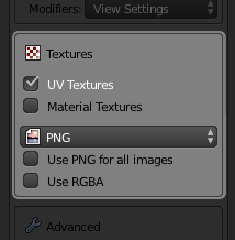
- UV Textures & Material Textures: Blender supports Material based textures and UV textures (which are directly assigned to polygons). Normally you want to export only the UV textures. In rare cases it is more desirable to export the material based textures instead. But beware, Blender does not export the render results, but only the source images!
- Image Type: The image format is typically predefined in the Blender Render settings. However we found it convenient to provide an immediate setting in the Exporter. By default the image type will be applied ONLY to generated images.
- Use ‘Image format’ for all images: If this option is set, then Blender will use the selected image format for all exported images. If the option is disabled, then only the generated images will be affected.
- Use RGBA: Blender can export the Alpha channel for images. Normally this is controlled in the render settings where you can specify to use either RGB or RGBA for image exports. If the currently selected export format supports Alpha then enabling RGBA here will export images with Alpha channel even if the render settings are set to RGB and vice versa.
Hint: You may want to NOT use RGBA because of the Alpha glitch. However this is not a general advice. There are many situations where using Alpha images is even recommended (for example when you want to create an Alpha mask).
Hint: If the format of the exported image(es) does not support an Alpha channel then the “Use RGBA” option is simply ignored.
Advanced options
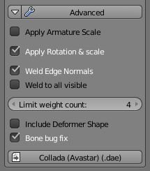
bone bug fix: We have found that some online worlds have serious issues with modified Joint offsets for Collision volumes and Attachments(1). Hence we suppress the export of joint offsets for collision volumes and attachment bones by default.(1): The technical details are related to the SL Importer’s option With Joint Positions The Skeleton can be modified (in edit mode) to create other rest poses than the default rest pose (T-Pose) When you do that, you actually move the Joint Offsets away from their default locations. And you will later have to set “with Joint Offset” during import in order to get your modified skeleton uploaded.
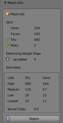
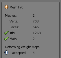
Mesh Info
The panel is organized in 3 parts:
- The Mesh Data statistics
- LOD Estimates (assumptions)
- Basic Quality Report
Mesh statistic
Statistic Details:
Meshes
In Object Mode: the Number of separate Objects in current selection. In Edit Mode: the name of the edited mesh is displayed.
Verts
Total sum of vertices for all selected after all modifiers have been applied.
Faces
Total sum of faces for all selected after all modifiers have been applied
Tris
Total sum of Triangles for all selected after triangulation
UVs
total sum of UV Vertices for allselected
Materials
The number of Materials used by the selected object with the most number of materials.
Note: Sometimes you may see values like for example “3 + 2” in the display. This indicates that the number of model faces assigned to a material (texture face) exceeds 21844. The SL Importer will then split the texture face(s) into chunks with no more than 21844 model faces and create one material for each of these chunks.The number of true materials is indicated in the first number (3 in the example). And the number of extra chunks is indicated in the second number (2 in our example)
Hint: This can potentially result in too many (>8) texture faces.
Deforming weight Maps
The number of found Weight Maps for the selected collection of mesh Objects.
Hint: When you click on the blue Info icon, then you get a more detailed report in a popup Message box.
Estimates
This section displays the number of Triangles and the number of effective vertices for the automatic generated LOD’s of the SL Importer.
Note: Only the High LOD triangle count is exact. The High LOD vertex count may differ slightly from what the SL Importer calculates. All other numbers are rough estimates. We do not know how the actual LOD calculations are done. We simply predict the numbers and this can fail at times.
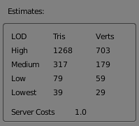
High LOD Tri count and Server Cost are correct. All other values are estimated.
Report
This button generates a summary report in the Blender console.
Following information is reported:
- Basic mesh data:
– polygons, modifiers, armatures, … - Weight group data:
– zero weight vertices.
– more than 4 weight groups vertices. - Any potential problems it finds.
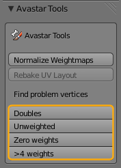
We have added a couple of vertex selection functions based on different rules. You find these tools in the Toolshelf (Avastar Tools Panel).
When you have selected only one single Mesh and that mesh contains vertices reported by the functions, then those vertices are selected (highlighted in yellow).
When you have selected multiple Objects you will find a report in the Blender Console with one line per object indicating the number of unweighted vertices.
When you are in Edit Mode or in Weight Paint mode, and when the tools find problematic vertices, then these vertices get selected (see image)
Note for Weight Paint Mode: When you use the tools in Weight Paint mode and when the tools detect problematic vertices, then the Editor switches automatically into Vertex mask Selection mode. You can leave this mode by deselecting the corresponding icon in the 3D View footer:
![]()

The tools
Unweighted/Zero weighted Vertices
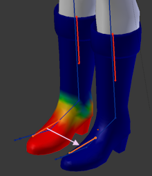
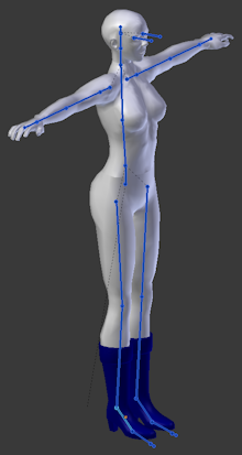
These vertices are not assigned to any of the Deforming Bones (unweighted) or assigned with a total weight of 0 to one or more Deforming groups (zero weighted). These vertices only move along with the movements of the mPelvis Bone.
When you pose any other bone in Blender then this appears like the unweighted vertices are simply “glued” to their RestPose Location (See image)
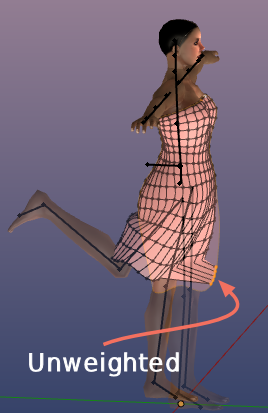
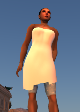
But nowadays the SL Importer will accept the mesh for import. However unweighted vertices will disappear when you wear the mesh, while zero-weighted vertices behave like in Blender
More than 4 weights per vertex
In Blender you can assign as may weights as you like to one single vertex. But in SL (and OpenSim as well) the maximum number of weights per vertex is limited to 4.
The Avastar Exporter will automatically reduce the number of weights per vertex. It simply removes the weights with the smallest weight values until the number of weights is 4 for the vertex.
Doubles (duplicate verts)
The Weight copy tool is used to copy the mesh weights from sibling meshes and from other bones within the mesh skeleton (rig). Actually we support Weight copy at 3 different places:
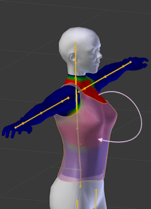
1.) While attaching a Mesh
During parenting a mesh to an Avastar rig you can enable an initial Weight copy from all visible siblings to all bones of the parented mesh. In the image on the right you see the armature (yellow) and the shirt(semi transparent) selected. Initial weight copy will project the weights of the upper body into the weights of the shirt. For more detailed information see the Reference guide
Binding(Assign to Armature).
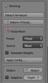
2.) While skinning a Mesh
Avastar supports 2 different skinning patterns for animating an SL mesh character:
- Via weighting the mBones
(also named Classic Weighting) - Via weighting the cBones
(also named Fitted Mesh Weighting).
Avastar can pre configure a Mesh to use either of the weighting patterns. For details read the Skinning section.
Note: Of course you can mix mBones and cBones manually. In that case you want to use the Fitted Mesh weighting Preset. For more detailed information see the Workflow
Skinning with Weight Copy
3.) Weight Copy Tools in Weight Paint Mode
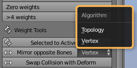
Note: The Selector in the Mirror Opposite Bones button is new with Avastar-1.3
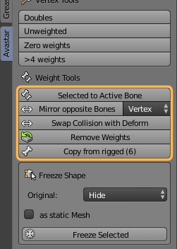
The Weight Copy Tool Reference
Below you find all Copy tools explained in more detail.
Selected to Active Bone
If you want to copy from another bone, then you must ensure that you have selected exactly 2 bones, where the source bone must be selected first while the target bone is SHIFT Selected second (so the target bone becomes the active bone!)
Note: The target bone’s weights will be entirely replaced by the weights from the source bone, not added or merged!
Mirror from Opposite Bone
If you want to mirror copy then you only have to select the target bone(s). You can select a set of bones. Avastar will perform the mirror function on each selected bone.
Note: If you have Sparkles-Pro (to be released soon), then you get one additional option Shape Mirror Copy which is less accurate but works in any case even if the topology is completely different on both sides of the mesh.
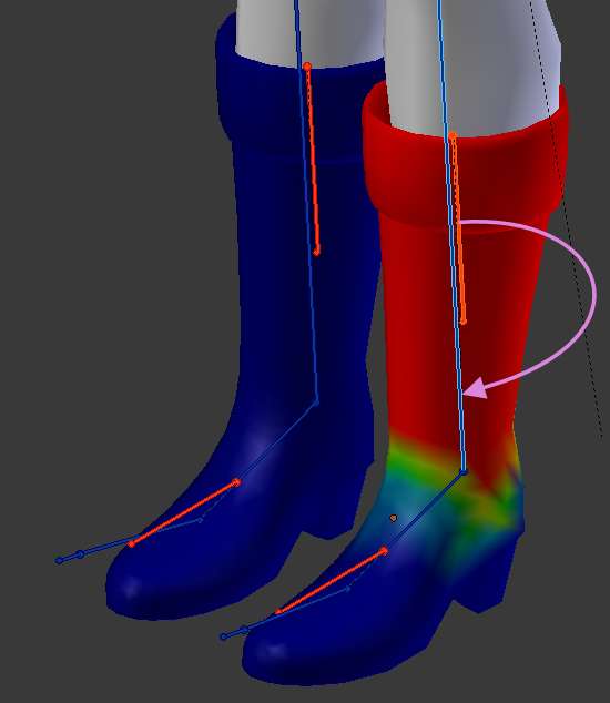
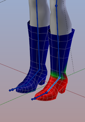
Details about Mirror Copy
The boots look pretty much equal, so you have the impression that a weight copy should be no big deal. But actually i have moved the left boot slightly out of symmetry, so all vertices have a small offset from perfect symmetry. And you can not see this slight asymmetry by just looking at it.
Lets assume you have carefully weighted the left boot and now you want to mirror copy the weights from the left ankle to the right ankle.
Whenever you see this happen you can be sure that your mesh is not exactly symmetric. In that case you can try a topology mirror copy, but unluckily this has its own pitfalls as well…
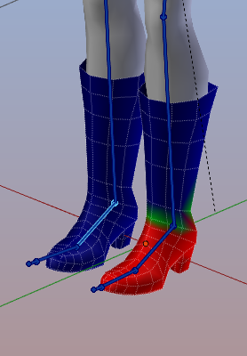
The problem with topology mirroring is that the used function needs a more complex mesh to identify the mirrored vertices. I have not fully understood how it works, but apparently it does not work for low polygon meshes, hence Topology mirroring is in general not suitable for game engine development.
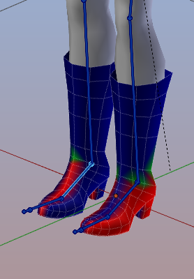
Stepping out of the pitfall
So if you have the situation that i just have explained above, then you have 2 options to proceed:
- Either you decide to use Blender’s Symmetrize function (in edit mode Mesh -> Symmetrize)
- Or you can decide to delete half of your mesh and use a Mirror modifier to fix this issue. Using the mirror modifier has the nice extra advantage that your weights get automatically mirror copied when you apply the modifier.
However, if you are working with slightly asymmetric meshes, then you might not be able to use mirror weight copy. Then you only can weight both sides of your mesh manually.
Sidenote: In our new Blender Addon Sparkles-Pro we have added an additional Shape Mirror Copy which is less accurate but works in any case even if the topology is completely different on both sides of the mesh. So if you are lazy and you want the one click solution, you may want to check out the Sparkles Pro tool.
Note: If you select a bone AND its mirrored bone, then only one of the bones will be mirrored. That is: We do NOT swap the weight data and thus you always end up with a symmetric result! This may not be what you want in all cases.
Swap Collision with Deform
Each classic mBone is related to a corresponding fitted mesh cBone. Hence when you select any of the Deform bones the tool knows which is the counterpart bone according to the table below.
Each time when you call the tool, the weights of the selected Bone(s) will be swapped with the weights of their corresponding counterpart.
The relation table
| Classic | Fitted Mesh |
|---|---|
| mCollarRight, mCollarLeft | R_CLAVICLE, L_CLAVICLE |
| mShoulderRight, mShoulderLeft | R_UPPER_ARM, L_UPPER_ARM |
| mElbowRight, mElbowLeft | R_LOWER_ARM, L_LOWER_ARM |
| mWristRight, mWristLeft | R_HAND, L_HAND |
| mHead | HEAD |
| mNeck | NECK |
| mChest | CHEST |
| mChest | UPPER_BACK |
| mChest | RIGHT_PEC, LEFT_PEC |
| mTorso | BELLY |
| mTorso | RIGHT_HANDLE, LEFT_HANDLE |
| mTorso | LOWER_BACK |
| mPelvis | PELVIS |
| mPelvis | BUTT |
| mHipRight, mHipLeft | R_UPPER_LEG, L_UPPER_LEG |
| mKneeRight, mKneeLeft | R_LOWER_LEG, L_LOWER_LEG |
| mAnkleRight, mAnkleLeft | R_FOOT, L_FOOT |
Important: The grey relations are not ambiguous thus they are ignored by the Swapping Tool!
Remove weights
Copy from Rigged
If you want to copy weights from other meshes (weight sources) to a mesh (weight target), then all source meshes and the target mesh must be siblings of the same armature. (all meshes must be attached to the same armature). All currently selected bones will become Copy targets in that case.
Note: Only visible weight sources are taken into account. Hence at least one weight source (mesh) must be visible.
Note: If you want to do a full weight Copy, then you only need to select all SL Bones (the blue ones) as seen in the image to the right.
Note: Custom meshes can also be used as Sources for a Weight Copy, provided they are siblings of the active Mesh!
Note: the topology of the source meshes and the target mesh may be different!
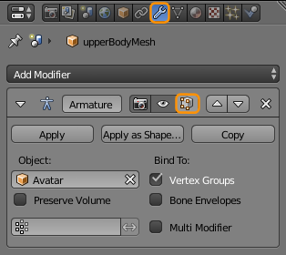
Binding (Assign Armature)
After you have modeled your mesh (Character or Attachment) the next step towards animating your work is skinning the mesh. This is basically the process of attaching the mesh to a rig (Armature) and defining how exactly the mesh gets influenced by the Armature’s Skeleton. Avastar’s Skinning Panel provides a convenient starting point for this work.
Basic Preparations
Cleaning up the Mesh
Ensure that the mesh does not have any implicit scale or rotation from one of its parent objects. This issue typically happens when your mesh is still parented to another object (Mesh, Rig, Empty,…) which has a scale and or rotation defined.
Easy Fix (recommended)
- Select the Mesh
- Object -> Parent -> Clear and Keep Transformation
- Object -> Apply -> Rotation and Scale
Advanced Fix (not recommended)
- Select the parent of the Mesh
- Apply Scale and Rotation
- Do the same for the Parent’s parent and so on…
This avoids unexpected behavior and it ensures that your object can be bound to another rig without distortions.
Hint: It is in general best to have as few objects as possible in your visible layer. So you best move all objects into another invisible layer which are not directly involved in the bind action. This ensures that you keep track of what happens.
Reposition and Bind
You prepare the binding step as follows: First you align your new mesh attachment as good as possible to the Avastar character. Then you select both the armature and the new mesh attachment:
- Go to Object mode
- Select the attachment with RMB. If you want to bind multiple new attachment at once, select all of them now (order does not matter).
- SHIFT RMB select the Avastar Armature.
Now you have selected the Rig and all mesh attachment which shall be bound to the Armature.

Note: If you are familiar with Blender, then you can simply parent the selected meshes to the armature (using Object -> Parent -> Armature Deform).
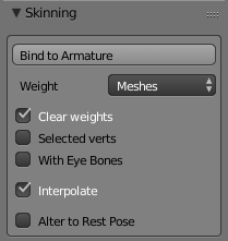
The Skinning Panel
The Weight Option allows to select from where the initial weight maps will be generated. The 5 check marks below the Weight Option provide more basic fine adjustment (see below for details).
Note: You can not expect that this function automatically creates optimal results! Hence you must be prepared that in most cases the resulting weight maps have to be fine adjusted manually. Please look at the Create an Attachment tutorial on this website.
The Skinning Panel Options
Weight:
This Property defines from where the Bound meshes will get their initial weights. We provide 4 Weight sources here:
Hint: The automatic weight assignment sometimes runs into an issue where it can not find solutions for one or more vertices. This is typically due to intersecting and/or unconnected mesh parts in your object.
This option will only create missing weight maps. Weight maps which already exist in the Mesh will not be touched and kept as they are.
Hint: The Empty option should be rarely used. In almost every case you will be better with the next option.
This option is almost identical with the Empty option, only you will not be cluttered with empty weight Maps. Since weight maps are created on the fly during your weighting activities, in almost every case this option is the best to use when you intend to create your own weight maps.
Note: Directly after a mesh was bound to an Armature, you will find this section replaced by a weight Generator section from where you can regenerate your weights completely or partially at any time. For more details see in the skinning help section.
Clear Weights
Selected verts
With Eye Bones
Interpolate (only available with Weight:Meshes)
Alter to Rest Pose
What is Alter mesh to Rest Pose ?
This video is about what the Alter to Restpose feature actually does for you
Below you find some explanation.
In principle this option does the equivalent of the following procedure:
- The current pose (“mesh pose”) is made the armature’s default pose.
- The mesh is parented to the new default pose
- The pose is set to the actual T-Pose (and the mesh gets bent into T-Pose)
- The mesh is frozen (pose applied and mesh unbound from the armature)
- The armature’s default pose is set back to T-Pose
- The mesh is parented to T-Pose.
- When now the armature is posed into the original “mesh pose” then the mesh looks exactly like it looked when it was not yet parented.
Note: Since Avastar is modifying your mesh directly, you should use this tool with caution.
- When your mesh fits well to the Avastar mesh, then you probably want to initialize your weight maps by setting the Weight option to “Meshes”.
- Only when you have to pose the Avastar in order to get a good alignment to your mesh, then you will also want to enable “Alter Mesh to Rest Pose”.
Note
When the option “Alter mesh to Rest Pose” is enabled then your mesh will be altered on vertex level. The mesh will actually be bended into the Avatar Rest Pose (which is the T-Pose). Such that when the current pose gets applied later then the current shape of the mesh is almost exactly preserved.
Freeze Shape
Purpose
The freeze either creates static meshes from your rigged meshes, or modifiable versions of your selected meshes. The tool basically removes all shape keys and all Avastar control data.
The Freeze Tool is used in following situations:
Usage
- Ensure Blender is in Object Mode.
- Select all parts which you want to freeze.
- Set the freeze options.
- Freeze Selected.
Details
Select all parts of the Avastar meshes which you want to use for your own character:
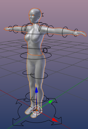
Here i have selected the Head, the upper body and the lower body
Note: The frozen Meshes do no longer react in the exact same way to the Avastar sliders as the original Avastar character does. However, the meshes behave exactly in the same way as they will behave when imported into SL, OpenSim or other compatible virtual environments.
What you should know
- When you select to Keep the Original, then the original mesh and your frozen mesh will overlap and you might not be able to see that there are actually 2 meshes now.
- When you select to Delete the Original, then the Original Avastar mesh is fully replaced by your frozen version.
- When you select to Hide the original, then the Original Avastar mesh will be hidden from view, then you only see the frozen version.
- when you enable Standalone Posed then your frozen mesh will be detached from the armature and it will end up as a simple non rigged static mesh.
- When you enable Remove Weight Groups then all weight groups of the frozen mesh will be deleted and you end up with a static non rigged mesh without any weights associated to it. (A naked model so to say)
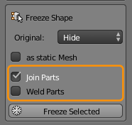
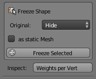
The Tool Options
Original:
This option defines what shall happen with the original Mesh(es) (those which you have selected in Object mode)
Values:
- Delete: The Original Mesh is deleted.
- Hide: The Original mesh is kept but gets hidden. You can always unhide hidden objects with the keyboard shortcut ALT + H
- Keep: The Original Mesh is kept and remains visible. Thus the original and the new copy are displayed at the same time
As static Mesh:
If the original Mesh was rigged to an armature, then -by default- the frozen mesh Copies keep rigged as well. But sometimes you want to get a complete static statue with no animation information at all. In this case you will select this option.
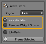
Note: If you select this option you get an additional option Remove Weight Groups which does what the name implies. Hence you can achieve that the frozen object contains no animation data at all (this option is rarely used, but very handy when needed)
Join Parts:
Note: If the Join parts option is selected, then you get one more option Weld Parts. If that option is checked, then all duplicate vertices along the adjacent edges of the joined parts will be merged.