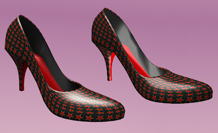
abstract: We now want to add some more complexity and add different color to different parts of our object.

In this chapter you will learn the basics of UV mapping and texturing.

Video Tutorial

To be done

Locating the Parts

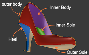
At the moment our material does not change along the surface of the shoe. It is simply red. Also its reflection properties are the same all over the surface. But this is oversimplified. When we look at a real shoe, we find at least following parts:

  • The inner & outer sole
  • The inner & outer body
  • The heel

Blender does not know how to break up a shoe into its parts. We have to provide hints where these parts are located on the model. We have to tell Blender in more detail how we want the different parts to be colorized.

Mapping the parts (The UV Map)

One very common method to add color and structure (aka texturize) is by using 2D images (textures). The image content is then mapped to the surface of the 3D object. In more detail it works as follows:

Remember the basic building block of mesh objects are Faces. Since faces are flat, projecting flat images on them is easy.

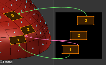
The image to the right illustrates the mapping from a flat image to the surface of a mesh object:

  • On the left side of the image you see the tip of the shoe within the 3D view. I have selected one single face of the shoe.
  • On the right side of the image you see a 2 dimensional (flat) image with a black background and one rectangle with the number “1” placed in its center..

The rectangle in the image is now projected on the selected face of the shoe. This projection is also called a mapping. The mapping is done on Vertex level: For each mapped Face actually its corner vertices are mapped from the image to the surface.

Note that the just described projection of one single face must be done for every face in the 3D view. At least if you want to cover the entire surface of your object.

Sometimes you will find that people make no distinction between “UV Texture” and “UV Map”. I think this is very missleading and i recommend that you take care here!

  • It is common practice to name the axes of the flat image “U” and “V”. This helps for a better distinction from the 3D axes in the 3D view, which are usually named “X”, “Y” and “Z”.
  • The flat image is typically named “Texture” and in our context it is often named UV Texture (because of the name “U” and “V” for the image axes).
  • An area on the UV Texture which maps exactly to a Face in the 3D view is named UV Face. In the image above we see one UV Face mapped to one Face on the object.
  • The mapping is actually the set of arrows which point from the UV texture to the 3D view. The entire set of arrows for one distinct mapping is also called UV Map.

Important: The UV Texture is an image. The UV Map tells how the image has to be placed (mapped) on the Object surface.

Some Observations

In this example (see image on the right side) i have mapped 3 faces.

Some remarks:

  • As mentioned before the mapping is done on Vertex level. Hence for each mapped Face actually its vertices are mapped.
  • Consequently corresponding shapes of the 3D face and the 2D face must have the same number of vertices, but can have completely different form. For example none of the faces in the 3D space are perfect rectangles, but all of them are mapped to perfect rectangles in the UV Texture.
  • Face 1 and Face 2 touch each other at one corner on the 3D Object. However the corner vertex can(!) be mapped to 2 separate locations on the 2D image. This is so because each 3D Face is mapped separately.
  • 2 adjacent Faces on the 3D Object can be mapped to completely different areas in the UV Map. They do not need to touch. They even can partially or fully overlap.
  • Take a closer look at Face 2 on the lower image. Do you see that this face gets mirrored on the Object surface ? Also see how overlapping areas of UV Faces on the UV Texture get mapped multiple times to the Model surface! There is nothing wrong with this UV Map!


The image below shows another (weird but fully legal) mapping:
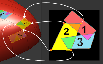
 

Note: In practice you will not define the mapping by hand, but use a set of ready available “UV unwrapping tools” for this task.

A Nasty Pitfall

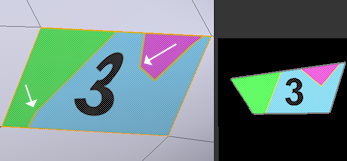
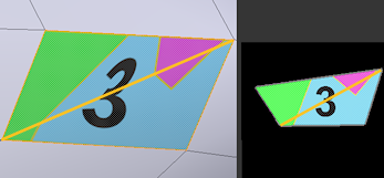
Take a closer look at the mapping of UV Face 3. The 2 white arrows point to areas of (maybe unexpected) distortion. Also the number “3” looks like it is too distorted. Why does that happen ?

When it comes to rendering, Blender converts Quads to Triangles. Actually you can see what happens when you draw the internally used triangulation on the image.


We see that the mapping can only be undistorted if the shape of the UV face matches the shape of the Face on the model. Otherwise the UV Triangles need to be stretched to cover the 3D Faces and that can result in distortions like seen here.


Note: The UV Unwrapping tools described below will help you minimize this sort of distortions.


Create a UV Map

In the previous chapter i have covered the most important details about the theory of UV Mapping. By now you should have a brief understanding of the topic. WEll, there is much more to say, but let us first see how we actually can create a working  UV Map and an associated UV Texture. That is what this chapter is all about.

Let us create a new UV Map for our  shoe model:

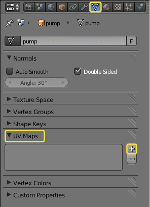
  • Select the Shoe and proceed to the Object Data Properties Section.
  • Locate the “UV Maps” tab
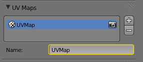
  • Press the white Plus sign to create a new UV Map with the default name “UVMap”.
  • As soon as you have created the new UV Map, the panel changes as seen in the image below:

Our new UV Map contains a very basic mapping (default mapping). All Quads of the model have been mapped to the same UV area. Let us open the UV Image Editor to examine this in more detail.

The default Mapping

  • Open the UV Image Editor in one window.
  • Goto edit mode in the 3D view
  • Ensure that you are in “Solid” display mode and you have enabled “textured solid” in the properties panel of the 3D View (Shading tab)

    If you do not work with GLSL mode, then you simply can switch to display mode “textured” instead.
  • Enable face select mode in the 3D View
  • finally deselect all faces.


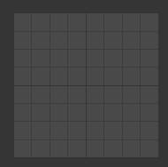
The UV Image editor gives you a visual representation of the Map. In the default display mode the image editor will show you only the map of the currently selected 3D Faces on your model. Since we have not selected any face the map is empty. Hence the UV Image editor should now display a dark grey square like shown on the image above.

Let us make the map visible:

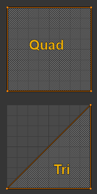
  • Select one single face in the 3D view (3D Face). You now see the corresponding UV face in the UV editor. The UV face either covers the entire UV-space if the 3D Face is a Quad (see upper image on the right)
  • or the UV Face covers only half of the UV-Space if the 3D Face is a Triangle (see lower image on the right)
  • Select any other Face on the model. You will see that each 3D Face has been effectively mapped to the same UV location in the UV space.

Can we already make use of this very basic UV Map ? Let us make an experiment…

The Star map (a creative approach)

We will now use the default UV Layout to make our first shoe texture. But beware that the process of texturing is with no doubt a complex task and you need to know a lot of details to get to appealing results. The following approach is typically not how you will do it in general. But it still gives you a lot of insight and maybe the one or the other idea here is just right for your project.

  • Upload the image on the right side to your computer. This is a simple image texture.
  • Now go to Blender and from the image editor import this texture with “image -> Open Image”…
  • Then select the shoe, go to edit mode and select all vertices.
  • Also ensure that you are in “textured” display mode
  • Finally select the just imported texture in the UV image editor.

right click, Save as
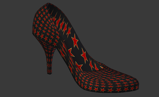
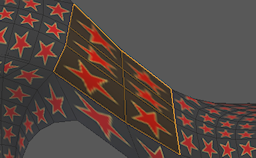
You should now see your shoe like here:

 We can see a couple of issues here:

  • Because each 3D Face is covered by the entire UV texture, we see as many stars as there are faces in the object. Hence the entire surface is now covered with stars.
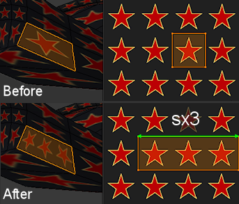
  • The size of the stars is only determined by the size of the faces. This leads to distortions as you can see in the middle part of the shoe for example.
  • Because the texture image has only limited resolution, we see a noticeable loss of precision when the 3D Faces get bigger. For example the faces in the interior of the shoe are much bigger compared to those on the outside. Thus their relative resolution has become lower and they look very blocky when examined in detail.


  • How can we achieve that only the outside of the shoe body gets covered with stars while the entire rest gets texturized differently.
  • How can we get more stars on big faces to compensate the face size ?

Adjusting the UV scaling

Let us first correct the wrong scaling on the shoe sides. Apparently we need more stars per face here and we can use the fact that the texture image is tilable. Fortunately Blender has a texture repeat mode:

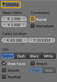
  • Open the properties panel of the UV Image editor ( press ‘n’ )
  • Locate the Display tab
  • Enable Repeat
Now the image editor shows an infinite repetition of the texture image. Proceed as follows:

  • Enter the 3D View in edit mode
  • Ensure that you are in textured mode
  • Select one of the faces which are too big and need adjustment
  • Switch to the UV image editor and select all (press “a” twice)
  • now you can scale the UV face in x and y until it contains enough stars. You also can move the UV face to shift the stars to the right/left

Do this for every face which has a wrong scale.


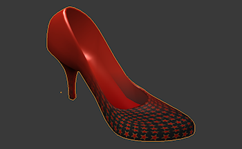
After tweeking the UV-Faces in the UV Image editor for a while, we end with an intermediate result similar to what you see on the image to the right. I have only corrected the outer part of the shoe body. I kept the other parts untouched.

Let us lean back for a moment and rethink about what we did. All we did was adjusting the scale of individual UV faces, because the associated 3D Faces where too big and thus the stars where stretched to the wrong size. But hold on, there is an alternative…

Alternative: Adjust the model

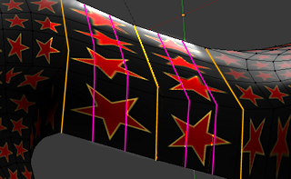
Instead of tweeking the UV Map, we could try to tweek the model itself! What about reducing the face sizes in the critical section of the shoe by splitting the faces up into smaller parts ? Lets try that by adding a few edge loops. Use ALT+r in edit mode and add edge loops as shown in pink on the image to the right.

But what a surprise! After splitting the big faces into smaller elements, the stars remain as big as before and they even span over different faces! (see image) What happened ?

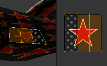
The reason is that Blender tries to maintain the UV Mapping when you add an edge loop. So it has automatically recalculated the mapping of the new created faces such that the mapping keeps as before. Lets take a look at the UVMap of the new faces. (in edit mode select the faces of interest, in the UV editor see the associated UV Faces)

We see that Blender has cut the UV Faces similar to how it has cut the 3D Faces when we added the edge loops. But actually we want each 3D face to cover the entire star.

The fix is very easy. We only need to “reset” the UV map. We do this as follows:

  • go to edit mode
  • select all faces
  • Mesh -> UV Unwrap -> Reset

Resetting a UV Map actually maps the entire UV space (the entire image) to each face of the object as decribed further above. As you can see now the shoe body is fixed regarding its texturing.

Fixing the texture on Model level has a price. In our case we have added faces, which is not always what you want.

Hint: Especially when you are creating models for game engines, your aim will be to get away with as few faces as possible. Thus you would prefer to do the extra work and tweek the UV Map instead of paying with more 3D faces.

Colorising the  other parts

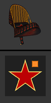
Now we get creative. We will use the very same star texture  to colorise the inner side of the shoe in black and the inner&outer sole in red. I will use a very simple trick here.

  • Select the inner part of the shoe body.
  • In the UV Image editor select all UV faces.
  • Scale the UV faces down and shift them to a black part of the texture image.

The result of this is obvious: All selected UV faces have now been colorised in black, thus the corresponding 3D Faces no longer show the star symbol. We can use the exact same trick for the soles.

  • Select the faces of inner sole and the outer sole
  • scale down and shift the corresponding UV faces to the red area of the star.

Now the soles are red.

Note that the shoe surface is now covered with a very small texture of size 128*128 pixels, but due to the repeated usage of the texture image its resolution is of very high quality. Below you see a comparison between the rendered image from Blender and the exact same model as it is displayed in a World Viewer. Which is which 🙂 ?


Chapter summary

 Here is what we did so far:

  • We described the principles of UV Mapping
  • We added a default UV Map
  • We applied a simple tileable texture image and adjusted the UV Map to get a simple but usefull result.

If you are curious you can make another experiment and work out how you can get similar results in your favorite game engine .

You have three options to proceed from here depending on your personal interests: